Skip to content

Astable-Final-circuit?
Astable - Final circuit?

This is the last circuit proposed as working for an astable multi-vibrator.
It's now time to understand why this can or not correctly operate and if some issues are still present.

Due to the presence of R and C for each branch we're sure that the timing feature is somehow guaranteed; but how exactly is a matter we're going to see.

As already said at the switch-on one of bjts surely goes in saturation before the other which is so forced to go to interdiction.
We added the capacitors not only to make a timer as proposed but to alternates the states for the outputs too.

Let's suppose bjt2 wins the lottery and goes to saturation: its collector drops form Vcc to nearly 0.2V.
Due to the transitory nature of this falling signal, the capacitor won't block it at first instance so that it (the drop of  ~Vcc) will be replicated at its other top which connects directly to base1, the new value of which becomes:

newVb1 = Vb1 - ~Vcc

...continue reading "Astable – The completion"

Astable-First-look
Astable - First look

What essentially is an astable circuit useful for?
Just by thinking at its behaviour it can be considered a rudimentary timer with its two outputs alternating between on-off states and one each other in opposition.

First of all let's take again a first look to the circuit we saw in the previous post, here beside.

The links between the collectors and the positive supply Vcc up, and between emitters and ground down are dotted to indicate missing parts.
Suppose bjt1 on the right is interdicted while bjt2 is in saturation: if we connect both the collectors and emitters directly to the supply lines then the bjt1 would be charged quite entirely by the power supplier with the risk (depending by the bjt) to disrupt.

This suggests us to put a resistor in each branch: we choose between collectors and Vcc.

...continue reading "Astable – The parameters"

NE555
NE555 on breadboard

What remains of monostable configuration is the retriggerable mode.

To be concise, the retriggerable version simply gives you the possibility to extend the period of the ON time, that we saw in the previous post fixed by the external components; this is done just by giving a new trigger input while the output is still HIGH.

What happens?
From that input instant a new period starts, and if no other triggering inputs occur, the output signal will continue to stay high for that fixed period of time more.

Because we talked about the necessity to have an input impulse with a duration far quicker than the output one, we assume it as a rule.

Now we must concentrate on the core of the discussion: how to get the signal retriggered.
In other words where we must act to get success.

...continue reading "NE555 as Monostable – Retriggerable"

Monostable-Diagram-NR
Monostable Diagram

Let's continue answering to the last question in previous post.
After the switch pressure, which we tie the trigger pin to ground with, we surely get the latching couple (S,R)=(1,0).

We asked for the next state: (1,1) or (0,1)?
It depends by us: first occurs if we keep the trigger pin to ground, otherwise the Set condition is set to zero just by releasing the switch.

It's worthwhile to examine these two possibilities, to better understand the timing issues involved.
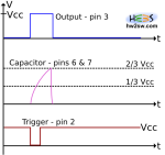
[Note that diagrams are not at the same scale: take a qualitative look]

Let's begin with the (0,1): this means that we release the pressure quite immediately.
By referring to the picture above we have in a bottom-up order the triggering event (which sets S=1), the charging of capacitor (until 2/3 Vcc which sets R=1), and finally the output which is quite-stable (and it's quite Vcc).
All this keeping in mind that the quick release of switch make S=0.

The result is obvious: output becomes high for an amount of time dictated by the charging time of capacitor through resistor(s).
After that it returns to the stable state, here the low one.

What happens by keeping the switch pressed?

...continue reading "NE555 as Monostable – How to"

NE555
NE555 on breadboard

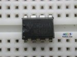
Maybe the most famous precision electronic timer of all times, NE555 was invented by Hans Camenzind (Switzerland) in 1970.

After more than 40 years it's still alive and healthy: born in the BJT's era now it is available in CMOS technology, even at low voltage (for more specific requirements) and in more than a package.

The interest about it never decreases, because of its simplicity and versatility.
And you'll find plenty of examples on the web with this IC involved.


By integrating both analogical and digital circuitry (very basic aspects) it is a bridge for the beginners to pass from discrete components to integrated ones with a good continuity level.

...continue reading "NE555"