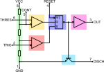
We're going a little bit deeper in explaining the NE555.
Don't worry about it; nothing difficult will be treated in spite of the complicated picture beside, which could announce a tremendously technical post.
We'll concentrate only on few points to explicate what written in the two previous posts about this IC, especially to see the underlying structure of the S-R latch.
Pins are clearly signed in the electrical scheme representation making easy to recognize them: to facilitate things, inputs 2 and 6 are on the middle-left, power on top-left and bottom-left, and output on the right.
Pin 5 which finally we'll talk about is conveniently going from near 6-threshold to the first node of the triple 5kΩ voltage divider.
