Skip to content

Monostable-Diagram-NR
Non-retriggerable

We're talking again of the monostable configuration: the timing calculation is the matter.
First of that we'd do better to have a closer look at the timing aspects.

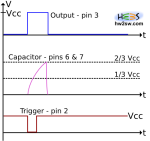
As clearly seen the couple resistor-capacitor in input to pin 6 fixes the amount of time during which the output is high.
The simple multiplication returns a time dimension, but it must be corrected by a factor (a constant) to be determined.

To do this please refer to the above image: again we have a temporal diagram with a hypothetical flow of signals involved, for a non-retriggerable monostable.
Now the time is the main matter: how to determine a correct value for the tON at output?
...continue reading "NE555 as Monostable – Time ON"

Monostable-Diagram-NR
Monostable Diagram

Let's continue answering to the last question in previous post.
After the switch pressure, which we tie the trigger pin to ground with, we surely get the latching couple (S,R)=(1,0).

We asked for the next state: (1,1) or (0,1)?
It depends by us: first occurs if we keep the trigger pin to ground, otherwise the Set condition is set to zero just by releasing the switch.

It's worthwhile to examine these two possibilities, to better understand the timing issues involved.
[Note that diagrams are not at the same scale: take a qualitative look]

Let's begin with the (0,1): this means that we release the pressure quite immediately.
By referring to the picture above we have in a bottom-up order the triggering event (which sets S=1), the charging of capacitor (until 2/3 Vcc which sets R=1), and finally the output which is quite-stable (and it's quite Vcc).
All this keeping in mind that the quick release of switch make S=0.

The result is obvious: output becomes high for an amount of time dictated by the charging time of capacitor through resistor(s).
After that it returns to the stable state, here the low one.

What happens by keeping the switch pressed?

...continue reading "NE555 as Monostable – How to"

MonoStable-Scheme
NE555 - MonoStable Scheme

What is a monostable?
And how can it relate to a timer IC?

As the word could suggest, it's something able to keep just one thing firmly.
For the NE555, or generally for a device, it must be intended as a condition itself.

But we know the name of the condition in jargon: state.
We talked about this concept introducing the S-R latch behavior indeed.

Well... in few words a monostable configuration simply means that 555 can keep stable only one between High and Low state. And to be precise the complete statement is monostable multi-vibrator.
Maybe what it has to be said is that in this case the output value matches with the state of the IC; but generally speaking these two concepts must be taken separately.
For our purpose we just consider them interchangeable.

...continue reading "NE555 as Monostable"

NE555-Internal-Circuit
NE555 - Internal Circuit

We're going a little bit deeper in explaining the NE555.

Don't worry about it; nothing difficult will be treated in spite of the complicated picture beside, which could announce a tremendously technical post.

We'll concentrate only on few points to explicate what written in the two previous posts about this IC, especially to see the underlying structure of the S-R latch.

Pins are clearly signed in the electrical scheme representation making easy to recognize them: to facilitate things, inputs 2 and 6 are on the middle-left, power on top-left and bottom-left, and output on the right.
Pin 5 which finally we'll talk about is conveniently going from near 6-threshold to the first node of the triple 5kΩ voltage divider.

...continue reading "NE555 – A deeper look inside"

NE555-Block_Diagram
Block Diagram (wikipedia)

We left last time with some questions about the working core of NE555.
Time to answer.

As we get a digital output from pin 3 (quite Vcc or ground) what about its generation?

We saw the input pins by which we condition the IC, particularly pins 2 (trigger) and 6 (threshold); for now leave pin 5 (voltage control) away.
We will talk about it when we'll have fixed the fundamentals inside our mind.

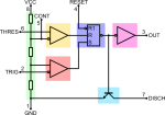
These two lines go directly to comparators, 2-trigger to the inverting input of the below one while 6-threshold to the non inverting of the above; and as said the comparators give high or low out signal if the voltage input difference is positive or negative respectively.

And finally, outputs to the S-R F-F (Set Reset Flip-Flop).

...continue reading "NE555 – A brief look inside"