Passive InfraRed Sensors now-days cost almost nothing and can be hooked up to arduino easily.
A PIR sensor can detect motion since it measures infrared (IR) light radiation from objects in its field of view.
More theoretical informations about the functionality of this sensor will be posted on later articles.
We will see two slightly different sensors based on the BISS0001 chip.
The datasheet of this chip can be downloaded from here : BISS0001.
The BISS0001 chip has two modes : re-triggering (H) and not re-triggering (L).
To keep it simple we assume that when our sensor detects motion a red light lights up.
In the re-triggering mode (H) the led does stay on the entire time that something is moving.
In the non re-triggering mode (L) when something is moving the led goes on and off every second or so.
In the most cases the re-triggering mode (H) is more suitable.
In AHA project we are going to use the re-triggering mode (H) mode.
Author: tasos
Infrared emitters & receivers
An IR Led emitter combined with an IR receiver can make an opto-isolator.
By using an opto isolator we can transfer information between circuits without an electrical connection.
In opto isolators the emitter is always an IR LED.
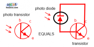
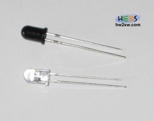
The receiver can be a photo-diode or a photo-transistor.
Photo transistors are transistors using the base as "light" sensor. When light strikes the photo transistor's base, it will conduct otherwise it will insulate.
Photo-diodes, on the other hand, are semiconductors that produce current flow when they absorb light.
There are two types of photo-diodes the photovoltaics and the photoconductors.
The photovoltaics when they absorb light create a voltage difference between the edges.
Photoconductors are reverse biased photo diodes. When they absorb light the reverse biased resistance will decrease.
Notice that a photo-transistor is nothing else than a reverse biased photo-diode + a normal transistor.
USB Microscope 20-800x presentation
A USB microscope can be useful for electronics or not ?
I was very skeptical before buying this gadget.
Everyone seems to use it for general inspection and not as a real time soldering equipment.
I have seen the excellent review of Todd Harrison which i highly recommend to watch before buying this gadget.
Two main things bothered me : how responsive would be on a fast desktop computer and if the distance between the microscope and the PCB board would be enough for soldering elaboration.
I bought this 800X microscope from e-bay and i must say that i was impatient to see its capabilities.
The package arrived today without a box. It came with a mini CD with the drivers a little stand, a calibration rule , a plastic cover for the lens and the microscope itself.
The given stand is without doubt an inspection only stand since the maximum distance between the microscope and the PCB can be few millimeters.
Connecting a magnetic reed door switch into arduino
A magnetic reed switch is a switch that change it's state whenever a magnetic field is present.
Magnetic reeds are cheap and really easy to find online.
They have a lot of practical uses like checking if a window/door is open or not.
We will use them in our A-H-A project.
There are two options of these magnetic switches.
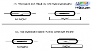
The N.O. (normally open) and the N.C. (Normally Closed) ones.
Normally Closed (NC) is a reed switch that the current passes when the magnet is not present.
The same type of reed is also called Normally Open with magnet.
On the other hand a reed switch is called NO, when without the presence of a magnetic field the current does not pass (open circuit).
The same type of reed switch can be also called Normally Closed with magnet.
In alarms it is most common to use a NO or alternatively called NC with magnet reed switch since the alarm when is broken or being cut by thieves then the circuit results open/broken even if the magnet (door) is in place.
That's why most residential alarm systems use NO or alternatively called NC with magnet reed switches.
More about reed switched will be discussed in other theoretical articles. If you are interested you can visit the dedicated wikipedia page.
Let's find out how we can connect this switch into an arduino board.
...continue reading "Connecting a magnetic reed door switch into arduino"
Connecting 125Khz RFID module to arduino – Part 2
In this tutorial we will see how we can recognize persons using our RFID reader.
Two LEDs will be added at the project in order to get some better user experience.
A "security line" will be also added. The concept of the "security line" is pretty simple.
If the line get's 5V (is HIGH) then arduino knows that the RFID reader is working correctly otherwise the RFID reader is broken (or the communication between arduino - RFID reader).
As always we will make an "object based" approach.
From the first article of RFID we can find the TAG IDs.
...continue reading "Connecting 125Khz RFID module to arduino – Part 2"