Skip to content

Serialino-and-Ethernet
Serialino and Ethernet

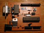
Finally we've got Serialino on the road.

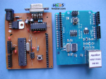
Two tests will be shown, about the simple LED blinking, and the code to drive an ethernet board put on it.

Just a quick note:  Serialino is already burnt with a ATMega328p compatible bootloader.
This will ease any code uploading.
Won't it?
Or not?

Not so indeed, or not the same like we feel working with a factory-made Arduino board.

The reason is that communication between Serialino and PC could fail under some undetermined conditions.

A very common problem that affects many home-made Arduino clones.
...continue reading "Serialino – Running Tests"

Serialino-PCB
Serialino - PCB

We talk again of Serialino, our Arduino's clone: this time the printed circuit board (PCB) design is shown.
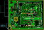
Here beside you find a screen-shot of the PCB of Serialino, numbered 1.0.

Even from here you should be able to distinguish the areas described in the previous post.

Power supply section on the bottom-left; the communication port and IC Max232 on the top-left; the headers on top and bottom; and finally ATMega with external oscillator, then the switch button and the ICSP pin headers.

...continue reading "Serialino – The PCB"

serialino-schematics
Serialino - Schematic

As promised last time, let's begin with the idea underlying Serialino's design.

Simply... we wanted to make everyone able to reproduce an Arduino-compatible platform at a reasonable cost, in a quite easy way thanks to the single-sided design, by focusing the communications with pc only on serial port, but without renouncing to an IC for this goal.

The choice of the IC relies upon the classical Max232.

And indeed the ATMega and Max232 are the core of the platform, the biggest components (in DIP format): as well as the ones requiring the major number of connections.

Here is the reason to center them inside the schematic.

...continue reading "Serialino – Design"

Serialino-top
Serialino - Top

Last time we talked about the importance of prototyping, when you decide to develop an idea involving electronics; this is worth especially if everything is direct to get the final result into a copper board.

The better the prototyping, the more efficient the copper board.

You know that the signal's integrity on breadboard is affected but multiple sources of noise: the capacitances and resistances due to the internal paths are just a little example, being negligible for standard circuits in DC or low frequencies power supplying.


Nonetheless you may want to know about it.

...continue reading "Serialino – Presentation"

In this short post we will see how to do a measurement of resistance when you have to test a grounding system and how to do a ground resistance measurement.

**Little theoretical summary**

One of the major causes of injuries and danger in the electrical systems are high failure voltages (rated value of the system plus the power surge), due to generally high failure current (look at this post) of systems. Those currents are usually drained to ground by grounding systems. It's easy to understand why you want the lowest resistance possible in the grounding system, merely:

RG = UG / IF            (1)

...continue reading "How to do a soil/grounding system resistance measurement"