
Passive InfraRed Sensors now-days cost almost nothing and can be hooked up to arduino easily.
A PIR sensor can detect motion since it measures infrared (IR) light radiation from objects in its field of view.
More theoretical informations about the functionality of this sensor will be posted on later articles.
We will see two slightly different sensors based on the BISS0001 chip.
The datasheet of this chip can be downloaded from here : BISS0001.
The BISS0001 chip has two modes : re-triggering (H) and not re-triggering (L).
To keep it simple we assume that when our sensor detects motion a red light lights up.
In the re-triggering mode (H) the led does stay on the entire time that something is moving.
In the non re-triggering mode (L) when something is moving the led goes on and off every second or so.
In the most cases the re-triggering mode (H) is more suitable.
In AHA project we are going to use the re-triggering mode (H) mode.
A cheap PIR sensor comes on a small board that contains the PIR sensor itself the BISS0001 chip in order to convert the analog signal (sensor) into a digital one and the lenses.
The lenses give to the PIR sensor much larger motion detection range.
Unfortunately the lenses come off easily so it is recommended to glue them with hot glue.
Take a look at the photo below
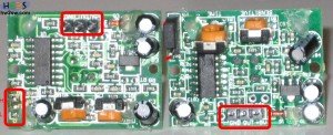
If you take a closer look these two boards are not same. The main difference is that the right one has a re-triggering jumper which must be set to High. The left one does not have the jumper but acts in re-triggering mode (H) by default.
Now it is time to set the sensitivity and the time from the dedicated trim pots.
I have found that the minimum settings on both trimmers worked better.
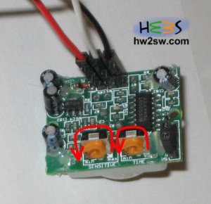
Use female to male or female to female and then male to male jumper wires in order to connect your sensor with the arduino board.
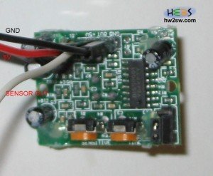
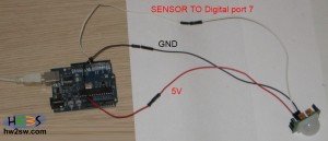
This connectivity works if you have a PIR Sensor that when detect motion the outputs 5V and when is not detection motion outputs 0V. Most of the ebay PIR sensors work with the connection above.
There are some PIR sensor (from sparkfun) having an open collector output , meaning that the sensor requires a pullup resistor so that the output is always high, and when the sensor detects motion it will pull the output low.
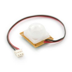
In this case the connection diagram is this :
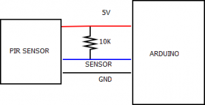
The dia diagram can be downloaded from here : ConnectivityDiagramPIR
In the next page we will see code examples for both ebay & sparkfun's PIR sensors