In this article we will talk about relays.
The relay is a device that permits with a small voltage to pilot a reed switch.
How this device should be applied on the circuit ?
How can we place it on an arduino ?
All these answers will be cleared in a while.
Let's start with some theory to see what happens in detail.
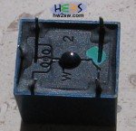
At the top of the relay we can see the 5V as input pilot voltage.
And we can see the 10A limitation at the 250VAC of the reed switch.
So with a 5 Voltage we can "switch" a 250VAC device that can consume up to 10A (P=V*I=2,5KW).
If you need to pilot a device that consumes more you should use a "bigger" relay that fit at your needs.
Before starting let's see the relay from the bottom.


You can see the inductance symbol.
At these pins you should apply the 5V pilot voltage supply.
Now what are the other three pins?
These are the pins used for the reed switch.

Normally two pins were enough for our needs. The third pin is used as a "NOT" port.
If you want that the relay is closed when there is no input voltage then you should use the pin NC normally closed. If you want that the circuit is open when there is no input voltage then you should use the NO normally open pin.
As you can see you will use only two pins of the three offered.
The relay should indicate which pin is NO and which is NC.
Normally means the relay condition without power supply.
After this discussion we are now ready to see the schematic of the relay .
 The empty circles are the pins of the relay. The black ones represent the reed switch.
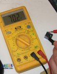
Every relay has an internal low resistance. From now on we will call that resistance Rr.
This one has Rr=70 Ohm.

The inductance L is needed in order to generate an electromagnetic field that can activate/deactivate the reed switch.
Here we see what happens when we do not have any input voltage.
No input voltage imply that we do not have any electromagnetic field and this imply that the reed switch is deactivated.
So It is in NC position.
Let's now see what happens when we apply voltage.

An electromagnetic field is generated. This field activates the reed switch and now "shorts" the NO path.
The equivalent electronic "charging" circuit is shown below

Notice the 5V battery as input. The T is a switch that is closed at time t=0.
The circuit is a common RL charging circuit.
We set Vo=5V as input voltage.
So we get
This is a differential equation of first order that it has been solved in this article
We know that :
So in our case we have
Now it is time to find C from the initial conditions.
For t=0 we know that I=0 so ... C=-Vo/Rr
So the solution for an RL charging circuit is :
In the next page we will see what happens after a lot of time ()