Now we press the button and voltage of trigger pin becomes Vcc: we get (S,R)=(0,1).
Now the capacitor can discharge because output and then discharge pins are low.
This apart, everything seems equal to the previous behavior, just reversed in the order.
But suppose to keep the switch button pressed... we have the discharging of capacitor, and after that nothing changes: in facts we lock the (S,R) to the (0,1) couple of values.
In other words, again we have established a new stable state!
We cannot distinguish a unique stable state anymore!
So apparently nothing is different form the previous configuration, which we named the correct.
This forces us to state that there's no really an absolute stable state: it depends by the configuration.
Indeed a clear approach wants the (S,R)=(0,0) as initial condition, and this is possible only if we tie the trigger pin to Vcc through a resistor: the output will be so low, avoiding bad surprises we'd certainly have with a high one at the start up.
Surely a good point!
Maybe some other considerations concerning a better sensibility of internal components to falling impulses rather than rising ones could help: too much deep for our goals.
But there's another reason that make us prefer the low state as default, at least for the NE555, and it relates to the pin 4 (the reset).
We'll see why in the next post when discussing about an important circuital variation.


Here beside we have to pictures showing the two configurations just discussed.
The first one is the correct version: as you can see the momentary switch button - at right - electrically separates the trigger pin2 (tied to Vcc through a 10K resistor) from ground.
Second one inverts the disposition, bringing us to face a behavior we cannot accept when dealing with a monostable multi-vibrator circuit.
As you can notice everything is unchanged but switch's and resistor's connections.
But after that, are all things as described or not?
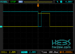
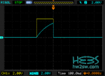
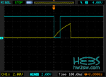
Take a look at the below screen-shots of measurements taken with the oscilloscope.
They refer only to the correct monostable configuration: because of the presence of max two channels for the oscilloscope we alternated the capture of signals to get three couples.
This necessarily is possible only with three different triggering pulses; not the perfection but surely enough to verify the goodness of what talked about until now.


[Power supply at nearly 5V; 2V/division for both channels. Correct configuration of monostable]
What else?
We don't know the duration of output impulse when high, which we're going to explain next time.
This we'll bring us to see another timing issue related to the triggering impulse, and we'll complete (if it's correct to say so) the talk of monostable timing features adopting an important variation.
Thanks!