Let's continue answering to the last question in previous post.
After the switch pressure, which we tie the trigger pin to ground with, we surely get the latching couple (S,R)=(1,0).
We asked for the next state: (1,1) or (0,1)?
It depends by us: first occurs if we keep the trigger pin to ground, otherwise the Set condition is set to zero just by releasing the switch.
It's worthwhile to examine these two possibilities, to better understand the timing issues involved.
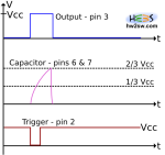
[Note that diagrams are not at the same scale: take a qualitative look]
Let's begin with the (0,1): this means that we release the pressure quite immediately.
By referring to the picture above we have in a bottom-up order the triggering event (which sets S=1), the charging of capacitor (until 2/3 Vcc which sets R=1), and finally the output which is quite-stable (and it's quite Vcc).
All this keeping in mind that the quick release of switch make S=0.
The result is obvious: output becomes high for an amount of time dictated by the charging time of capacitor through resistor(s).
After that it returns to the stable state, here the low one.
What happens by keeping the switch pressed?
The Set remains high and it doesn't feel any change in its state: when the voltage onto capacitor reaches the 2/3 Vcc value, then the Reset becomes 1, even with Set=1 still too.
We have what for a normal S-R latch is a non-allowed state, but which is accepted by the NE555 thanks to its internal design.
And we know this results into an overriding of the Set condition against the Reset: in other words, the output still remains high.
Then ideally fixing the button pressed we meet a new stable state.
What?!
All we've discussed about until now requires the low state as the default stable one.
Again we'd know better analyzing this situation too but making the high state as stable from the beginning, so answering to the question why we consider the low and not the high state as the stable.

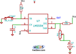
Very quickly: suppose the pin2 is tied ground or generally to a value less than 1/3 Vcc (so you should exchange the switch and the resistor in picture beside) while we can tie it to Vcc by pressing the switch; in other words we revolt the trigger configuration, with everything else kept unchanged.
Due to this choice output will be stably high at the start up of the circuit, thanks to the Set=1 condition.
If you remember we said that pin 3 (output) and pin 7 (discharge) are in phase: or if you prefer, when the first becomes high/low then the second does the same.
And by looking at the picture we see pin 7 is shorted with pin 6, both of them connected at the top terminal of capacitor (through a resistor, but the core of talk is still valid): well, the capacitor is charged!
And obviously Reset condition is latched at 1!
We have the (S,R)=(1,1) condition again.