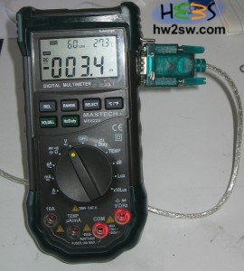
We have seen in this article how to hack fiscally our multimeter.
Now we have to start building our software in order to parse the 14 byte hexadecimal string into something more human.
The knowledge of bitwise operations is highly recommended and specially the masking technique (bitwise AND).
It is now time to start !
From the FS9721-LP3 documentation we clearly see that we get as response from the device a 14 byte code.
Each byte of this code has this structure NNNNXXXX where NNNN is the number of the segment of the table.
The reported table below has 14 segments (seg1-14).
The XXXX part reveals which bits of the NNNN segment are active (1 = true) or not (0= false).
We immediately understand that a correct code should be 1X 2X 3X 4X 5X 6X 7X 8X 9X AX BX CX DX EX since all the segment columns of the table should be filled.

Time for an example. If the first byte of the 14-byte code is 17 (in hex) means that we are talking about the segment 1 (which is correct) and the settings for this first segment are 7 (in hex) or 0111 in binary.
From the table we discover that RS232,AUTO and DC should be on and AC off.
With a little more attention we can see that a digit can be defined as a byte of two parts
For the first digit for example :
X,a5,a6,a1 -> from the segment 2 (we ignore the minus)
and
a4,a3,a7,a2 -> from the segment 3
The same is valid for the 2nd digit
X,b5,b6,b1 -> from the segment 4 (we ignore the dot)
and
b4,b3,b7,b2 -> from the segment 5
and so on ...
So a digit can be translated into a byte like this : X,a5,a6,a1,a4,a3,a7,a2 [X we ignore it. It is the negative sign or the point]
An example : Let's say that we want to design the digit 1 .
This means from the table that a2 and a3 bits are true and all the others are false so we get X,0,0,0,0,1,0,1
If you have understood this mechanism you are ready to write your code !
In the next page we will discover our data structures in order to create a "programmer friendly" code.