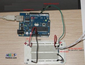
In this demo we will use the internal red led at digital port 13 of our arduino board.
The N.C. reed switch is connected to digital port 6.
The circuit is below :

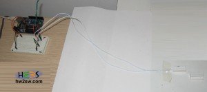
Below we can see a more generic view of the same circuit :

Here is a simple demo code :
int Door_Led_Pin = 13;   // choose the pin for the LED
int Door_Sensor_Pin = 6; // choose the Door_Sensor_Pin
int val = 0;             // variable for reading the Door_Sensor_Pin status

void setup() {
  pinMode(Door_Led_Pin, OUTPUT);    // declare Door_Led_Pin as output
  pinMode(Door_Sensor_Pin, INPUT);  // declare Door_Sensor_Pin as input
}

void loop(){
  val = digitalRead(Door_Sensor_Pin);  // read Door_Sensor_Pin
  if (val == HIGH) {         // If Door_Sensor N.C. (no with magnet) -> HIGH : Door is open / LOW : Door is closed
                             // If Door_Sensor N.0. (nc with magnet) -> HIGH : Door is closed / LOW : Door is open [This will be our case in AHA Project]
    digitalWrite(Door_Led_Pin, LOW);  //Set Door_Led low
  } else {
    digitalWrite(Door_Led_Pin, HIGH);  //Set Door_Led high
  }
}
As we can see when the door is open then the red led off and when the door closes then the red led is on.
The code can be downloaded from here : Reed_Switch
A video demonstration is posted below
In the next article we will see how we can connect a motion sensor into arduino.
Stay tuned.