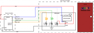
In this article we have seen how we can connect a led with arduino.
We will make exactly the same circuit using 1K pull down resistors.
The security line is nothing else but a button that is always pressed (on).
We have seen this circuit in this article.
The hole schematic is below :

This schematic was made using dia. The original file can be downloaded from here : AHA Diagram
Notice the physical separation between the secure zone and the not secured zone (door).
We need 6 cables between arduino and the RFID box. (+5V,GND,RFID_TX,SECURITY,GREEN,RED).
The only problem left is the RED led. Why ?
Because the RED led can blink in some cases but in the meanwhile arduino must be able to receive signals from the RFID reader.
For example "John" an "Authorized person" of the "house" arms (activates) the house in order to leave (within the "Max_Duration_To_Exit_Home" duration) but immediately remembers that the glasses are still in the house.
So needs to un-arm (deactivate) the alarm since can not exit within "Max_Duration_To_Exit_Home" .
The RED led blinks but John must deactivate the alarm !
As we can understand by this use case we can not applicate the normal blink with the delay command.
We strongly recommend to read this article directly from the arduino web page.
The "BlinkWithoutDelay" example comes bundled with the arduino GUI.
Can be loaded from : File -> Examples -> Digital -> BlinkWithoutDelay.
Based on the "BlinkWithoutDelay" we made our own code :
  ////////////////////////////////////////////////////////////////////////////////////////////////
  //SET LEDS BEGIN

  if (My_House.Is_Alarm_System_OK == true) {
    if (My_House.Is_Alarm_Activated == true) {

      digitalWrite(Green_Led_Pin, LOW);   // turn the GREEN LED off

      /////////////////////////////////////////////////////////////////////////
      //Blink async RED light BEGIN
      Current_Ms = millis();

      Red_Blink_Interval=1000;
      if(Current_Ms - Previous_Ms > Red_Blink_Interval) {
        Previous_Ms = Current_Ms;

        if (Red_Blink_Duration_Ms < My_House.Max_Duration_To_Exit_Home) {
          if (Red_Led_State == LOW) // if the LED is off turn it on and vice-versa:
            Red_Led_State = HIGH;
          else
            Red_Led_State = LOW;

          digitalWrite(Red_Led_Pin, Red_Led_State); // set the RED LED with the Red_Led_State of the variable
          Red_Blink_Duration_Ms = Red_Blink_Duration_Ms + Red_Blink_Interval;

        } else { //Time to exit passed the limit !
          digitalWrite(Red_Led_Pin, HIGH);
          Serial.println( "ALARM ACTIVE ! In this portion of code we will put the sensors to trigger the alarm" );
        }

      }
      //Blink async RED light END
      /////////////////////////////////////////////////////////////////////////

    } else { //Alarm is deactivated by authorized person
      digitalWrite(Green_Led_Pin, HIGH);   // turn the GREEN LED on
      digitalWrite(Red_Led_Pin, LOW);      // turn the RED LED off
      Red_Blink_Duration_Ms = 0; //reset the red blinking duration !
    }
  } else { // the alarm is broken

    digitalWrite(Green_Led_Pin, LOW);   // turn the GREEN LED off

    /////////////////////////////////////////////////////////////////////////
    //Blink async RED light BEGIN
    Current_Ms = millis();
    Red_Blink_Interval=100;
    if(Current_Ms - Previous_Ms > Red_Blink_Interval) {
      Previous_Ms = Current_Ms;
      if (Red_Led_State == LOW) // if the LED is off turn it on and vice-versa:
        Red_Led_State = HIGH;
      else
       Red_Led_State = LOW;

      digitalWrite(Red_Led_Pin, Red_Led_State); // set the RED LED with the Red_Led_State of the variable

    }
    //Blink async RED light END
    /////////////////////////////////////////////////////////////////////////

  }
  //SET LEDS END
  ////////////////////////////////////////////////////////////////////////////////////////////////
Notice that the blinking duration is 1000 ms in the exit countdown case and 100 ms in the alarm broken case.
In the next page we present the hole code and a video demonstration as always.