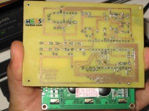
Once finished with the PCB board we have to take a look at the part list.
Here is the component list
| 2N2222 NPN
| C1 10u
| C2 10u
| C3 0.1u
| C4 22p
| C5 22p
| D1 LED
| D2 DIODE 1n4001
| D_LCD1 DISPLAY_MCG1602D
| IC1 ATMEGA328P-PU
| K1 RELAY_2RT 5V
| P1 12V
| P_LOADCELL1 1KG or 20Kg
| P_VALVE1 CONN_2 (12VDC Gravity feed)
| R1 330 (for the led you can als use a 1K resistor)
| R2 10K
| R3 10K
| R5 10K
| R6 10K
| R7 10K
| R9 1K
| R4LCD1 360-1000 (lcd contrast)
| R8GAIN1 10-400 (depends by the load cell used)
| SW1 SW_PUSH
| SW2 SW_PUSH
| SW3 SW_PUSH
| U1 7805 5V voltage regulator
| U2 INA125
| X1 16Mhz
Before starting to put the components on your board you should use some pins headers.
A male 2-pin header for the input voltage. Alternatively you can use a DC jack
A male 2-pin header for the gravity feed valve. By doing this you can easily connect and disconnect your valve.
Use a 2-pin header male or female for the RG gain resistor. This will help you to change easily the INA 125 gain.
A 4-pin female pin array for the load cell jack. Pay attention at the colors/connection.
A 2-pin male header for the RLCD for the lcd contrast. Again this resistor with this trick can be changed faster.
A 16-pin female pin array for the LCD. With this trick you can change the LCD at any time.
A 28-pin socket for the ATMEGA chip
and a 16-pin socket for our INA125 amplifier.
By soldering the sockets you don't risk damaging ATMEGA and/or INA 125.

Below we can watch how we have soldered our components :
A fully functional result is shown below :

At this point we are in position to construct our weight board.