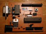
Last time we talked about the importance of prototyping, when you decide to develop an idea involving electronics; this is worth especially if everything is direct to get the final result into a copper board.
The better the prototyping, the more efficient the copper board.
You know that the signal's integrity on breadboard is affected but multiple sources of noise: the capacitances and resistances due to the internal paths are just a little example, being negligible for standard circuits in DC or low frequencies power supplying.
Nonetheless you may want to know about it.
To convert prototypes into more compact boards, a different approach is required from the more rudimental one used on breadboard: from the CAD drawing, finally to the work for the board's electrical tracks and components soldering.
Far away from a matter of pure pride and ability, the realization on copper transpose you into a different way of thinking: no project design can be affordable without a minimum direct experience of it.
In facts, requirements like board's final sizes, positioning of components (due to size, function, heat consumption and dissipation, and so on), cost of components, minimum width of electrical tracks, etc... are a good gym to design something to be run, especially in terms of commercial realization.

This last aspect means a lot of things, and it becomes vital when you design for a project that must be compatible, or "simply" must interface with an already existing product.
That's the case we're presenting here, of an Arduino clone, whose scheme has been shown in the last image of previous post, and again beside.