
MASTECH MS8229 is a 5 in 1 multimeter with excellent value for money rate.
By reading this post we have found that the IC used by this multimeter was the : FS9721-LP3.
This chip has RS232 output capabilities. The data-sheet can be downloaded from here : FS9721-LP3
The idea here is , starting from the IC documentation, to hack this multimeter, extract the data via RS232 and with the help of a dedicated software to be capable to do data logging.
This will be a hardware to software approach.
The pages 13 and 14 of the data sheet describe the transmission protocol.
Based on these two pages we will produce later our software application.
In the page 15 we can clearly see how we must hack our multimeter in order to output our serial data.
For this hack we are going to need
- Kynar wire 30 AWG
- An opto isolator based on photo−transistors i have used the TOSHIBA Photocoupler TLP620−4 since that i had available
- 10K resistor (not 1K)
- 220 Ohm resistor
- Serial db9 connector
- A toggle Mini Switch
All this stuff can be found on e-bay and amazon.
Before starting i must say that i started the hack by using the IR LED / photo - diode method but gave me pretty poor results so i opted to the opto isolator method. Using a R30 of 1K only i had hard time with the decoding since i received a lot of errors.
Using a 10K resistor solved that problem .
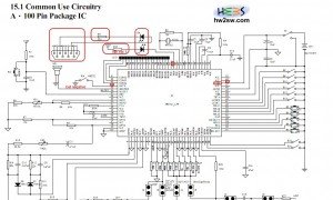
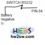
The first step is to add the toggle switch in order to enable and disable the RS232 option.
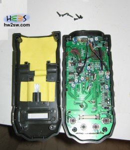
Open the multimeter by removing the green plastic case and unscrewing the 6 back screws
Using the USB microscope i managed to take good quality pictures before the hack.
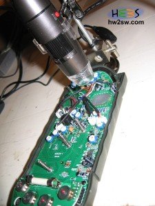
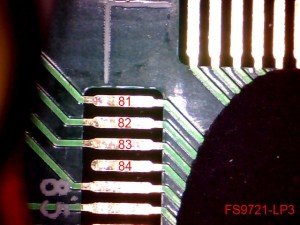
Now it is time to solder the pin 84 with the kynar wire. Notice that the pin 84 does not go anywhere 😉
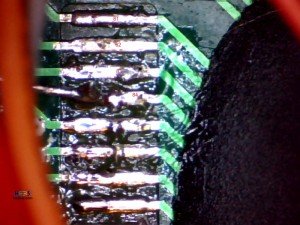
Now with another wire we solder the V- spring
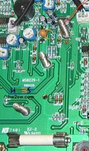
Once soldered these two wires it is time to drill the holes for the switch and the DB9 connector.
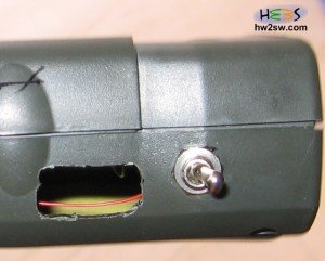

Notice that by placing the holes in these positions i did not had to remove any internal components.
The case was able to close without any extra force.
Once drilling the holes insert the switch and solder the two wires into the switch.

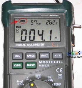
Now you can test the switch. By turning it on you should get a RS232 indication on the screen,
if not, then recheck your wires and connections.
The second step is in the next page ...